ARIS’ First Engine Firing – Project RHEA
Separator
It was a cold winter night in Ochsenboden, Switzerland, after 15 months of hard work: The whole team RHEA stared out of a bunker’s small slits in silence as the countdown started to run down. The pulse increased faster and faster until the heart beat was the only thing we perceived in our heads.
Three. Two. One. The ignition started, the opening of the main valve was signalled with a click, and before we even realized what we’re about to see, a bright shining exhaust flame exited the nozzle and turned the night into day.
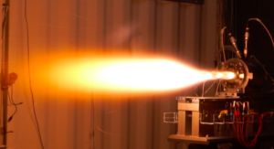


RHEA Hybrid Rocket Engine
Ever since the founding of ARIS, it has been clear that commercial solid rocket motors are only a temporary solution. In order to go higher and faster, in-house development of an engine would be needed. Therefore, project RHEA was established in September 2018, with the goal of setting a foundation for ARIS’ engine developments.
Due to the high intrinsic safety, good performance and research potential, it was decided to develop a hybrid rocket engine. In this first phase, even more important than the engine itself, was the development of a testing infrastructure. This infrastructure would allow ARIS to test and refine its engines for years to come.
ARIS’ First Engine Firing – Project RHEA
The infrastructure was segmented into three compartments: a 10 ft shipping container is used to house the data acquisition and control electronics. A larger 20 ft container contains the fluid supply system and lastly, behind a thick steel shielding wall sits the engine compartment.

Engine Compartment
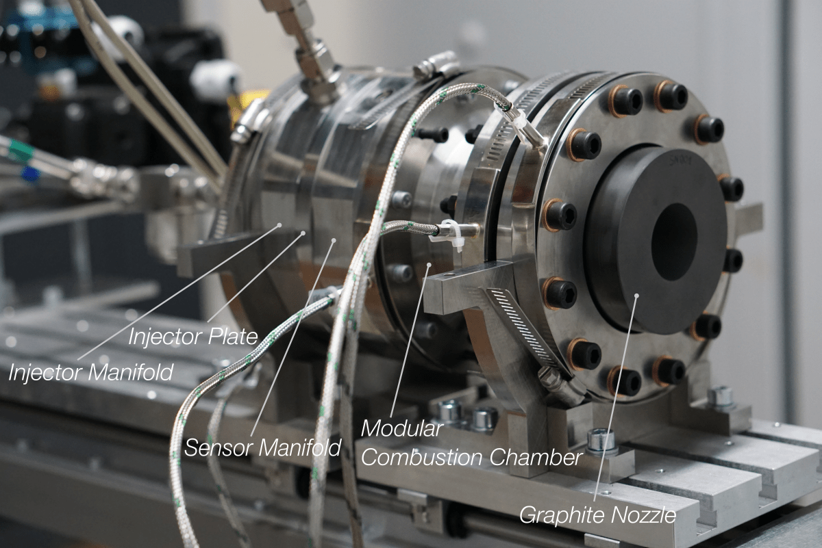
The hybrid rocket engine design is based on a combination of paraffin wax as the fuel and liquid nitrous oxide as the oxidizer. The combination was chosen because of the fast burning rate of the paraffin fuel and its future potential for enhancing its specific impulse with additives. Nitrous oxide is comparatively safe and easy to handle, requiring not cryogenic plumbing or highly corrosion resistant alloy combinations.
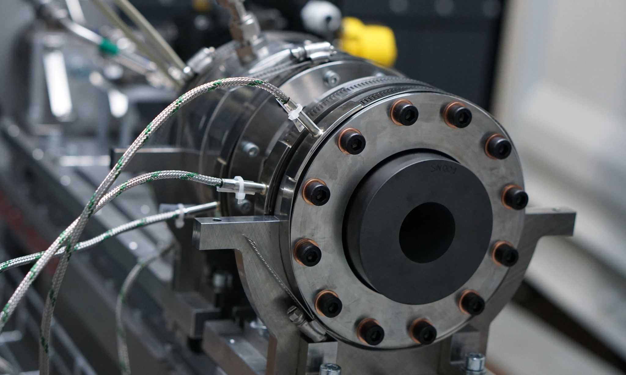
Project RHEA’s engine was developed as a test article with high safety factors and a modular construction. This means that the injector and nozzle can easily be swapped out, or the combustion chamber length be changed. That way, the engine allows for rapid testing and optimization of configurations on the order of 1 kN thrust.
On the test stand, the engine’s thrust, injector and chamber pressure as well as temperatures at several points are measured.
Fluid Supply System
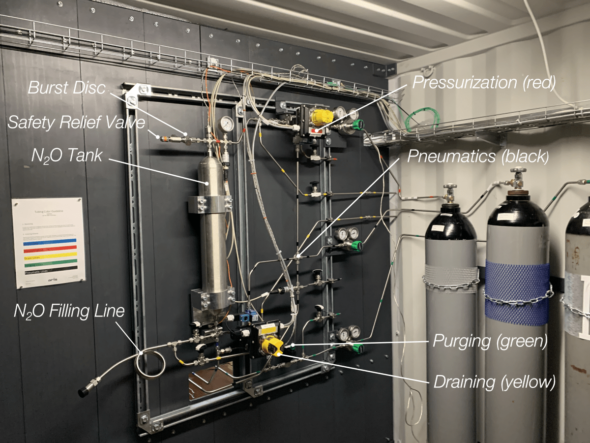
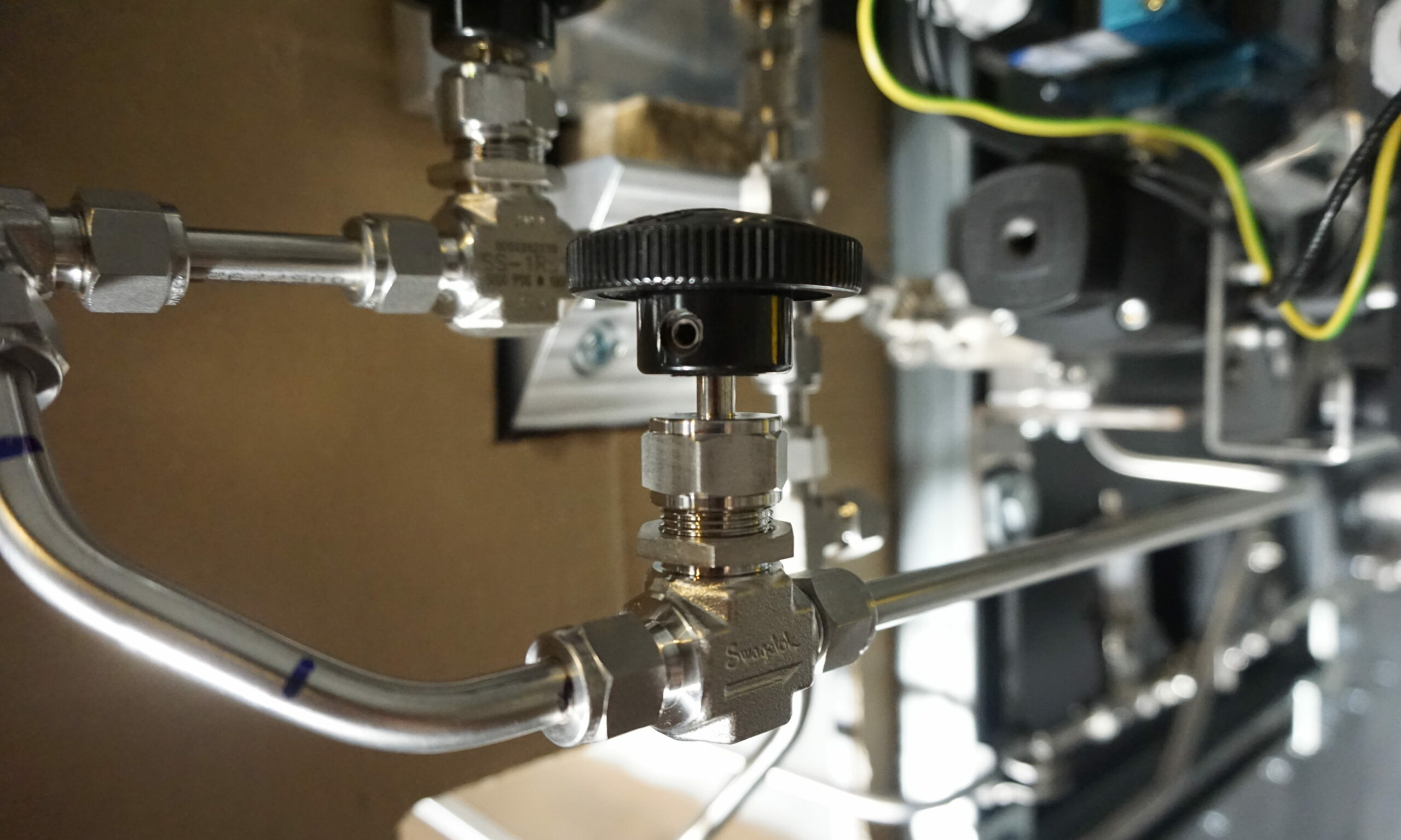
Nitrous oxide is supplied to the engine by the fluid supply system. 3 kg of nitrous oxide can be loaded into the tank which is sufficient for up to 10 s of firing duration. An external pressurization system uses nitrogen to pressurize the oxidizer up to 80 bar. While nitrous oxide can self-pressurize, an external pressurization system yields more constant conditions and increases safety by preventing cavitation in the liquid nitrous oxide, which might cause exothermic decomposition.
Pneumatic lines supply pressurized nitrogen to the valves that control tank pressurization, firing and tank drainage. After firing, combustible gases are purged from the engine by an additional nitrogen circuit. All subsystems of the fluid supply system are monitored with thermocouples and pressure transducers.
Electronics Compartment
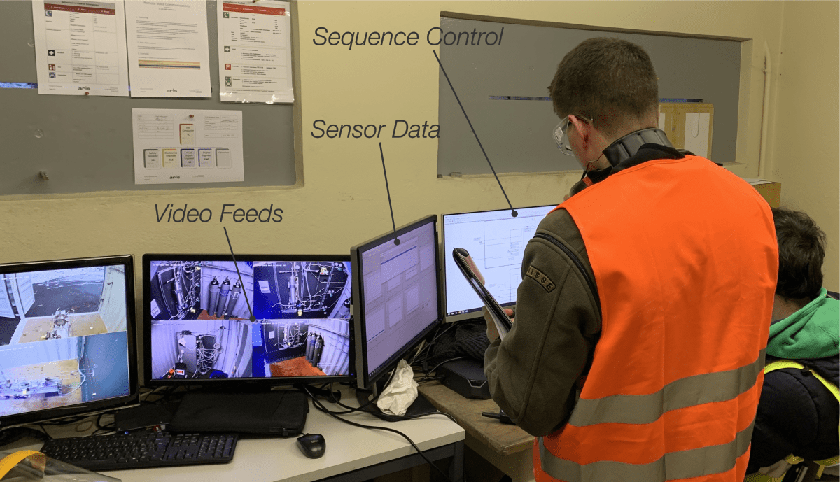
A large sever rack inside the electronics container provides space for the power supplies and relays that power the valves and ignition system. Control is assumed by a NI cRIO system that gathers all signals from thermocouples, pressure and force transducers from the other compartments. Based on those values, the cRIO system autonomously sends control signals to the relays which in turn precisely sequence the valves. Instructions to the cRIO system are sent from a bunker, where the team is protected by a 1 m thick concrete wall. Thin slits of bullet-proof glass give the operators a live view over the compartments. A video surveillance system provides additional angles and close-up views of all subsystems. All sensor data is shown live to the operators. For redundancy on the most critical sensors, some camera feeds also show the pressure indicated by analog pressure gauges.
The operators can manually override any action of the automatic control system. In addition an emergency shutdown system can be actuated. This physically cuts off the signal path from the cRIO and automatically returns the system into a safe, depressurized state.
ETH HÖNGGERBERG – ZURICH
Test Containers
It was a moment of great joy when the containers arrived at our basis at ETH Hönggerberg. First, the 20ft container for the engine and FSS followed by the smaller 10ft container for data acquisition.
ETH HÖNGGERBERG – ZURICH
Assembling the system
During June and July 2019, the system was united. First, the shielding plates, which separate the engine and FSS compartment, and the testbench were integrated, followed by the FSS system and cable trays. In parallel, the electronic boxes were assembled.
RHEINMETALL DEFENCE – OCHSENBODEN
Test campaign
The system assembly was finalized in October 2019, and the facility was moved to Ochsenboden for the testing campaign in November and Decemeber 2019. After completing the dry test and a cold flow test, the rocket engine finally got fired in December 2019.
The Test Location
Safety comes first. Besides many measures in the design and operations, an additional fall back was included by firing from a dedicated testing site with a bunker in Ochsenboden on the property of Rheinmetall Air Defence. The team stepwise moved closer to the firing by weekends of dry running the system, component-wise and then combined, functionality checks, a successful cold flow test.

Performance Data
A first firing was performed using 1.5 kg of nitrous oxide oxidizer, 10 mm pre- and post-combustion chamber length, a fuel grain with a cylindrical port and a showerhead injector, yielding 3.5 s of burning time, 838 N of peak thrust and a chamber pressure of 25 bar.
A second firing was performed with a swirl injector which yielded a higher peak thrust of 1253 N. Due to the higher discharge coefficient of the swirl injector, the oxidizer mass flow into the combustion chamber increased and thus the regression rate of the grain.
The Team
The team consisted of 9 students with the goal to bring ARIS closer to a fully self-developed sounding rocket by building and testing ARIS first hybrid rocket engine together with its infrastructure.

Without you we would not have succeeded
The successful completion of project RHEA would not have been possible without the tremendous amount of help we received through our academic and industrial partners.
Special thanks to ETH Zürich and the IDSC headed by Prof. Lino Guzzella for sharing knowledge, providing infrastructure and supporting the project financially. Furthermore, we want to thank Swagelok for their supply of all our fluid supply system parts and helping us with their expertise in selecting and installing the components.
We are most thankful to Maxon for manufacturing all our parts as well as Rheinmetall for giving us the unique opportunity of using their test location, Werner Steiger Stiftung for their support and RUAG Space for reviewing our designs.





Social Contact